
|
|
|
Implementing iCatcher
Learn how to implement an iCatcher system, from single camera residential to multi-camera - multi-site. read more... Sample iCatcher SitesMany thousands of people around the world use iCatcher software. See iCatcher images live. read more... Wildlife picture galleryi-Catcher Wildlife captures fantastic scenes from nature. Have a look at some of the best. read more... Capture equipmentFind out about suitable equipment for use with iCatcher, from cameras to lighting, and more. read more... iCatcher Business PartnersWould you like to learn more about how to do business reselling iCatcher solutions? read more... |
iCatcher & Home Automation Controlling devices and access with iCatcher iCatcher Console includes a full-featured device control and automation system that supports a wide variety of control systems. With the software it is possible to associate input changes with actions, and alerts with device control. An example of this is to turn on a light when motion is detected on a camera. 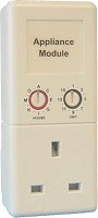
Supported systems iCatcher Console supports a number of commonly used access and device control/sensor systems:
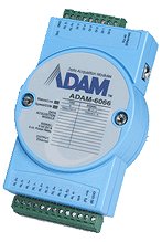
I/O Control Through suitable control devices (e.g. the ADAM I/O controllers and Axis devices), iCatcher can interface to more complex electronic systems. I/O Port devices allow iCatcher to set the state of a signal line, which can be interpreted as required by any connected system. We use an Axis 241Q with a Velleman relay board to control our lights and fan setup. We have also constructed a 4-way remote controllable power strip using an ethernet-over-power device and an ADAM I/O block. Sensor Inputs & Reactions iCatcher Console can respond to sensor inputs in a number of ways. A simple on/off electronic sensor can be used to instigate a series of actions. Similarly, analogue sensors (such as the Digi sensors) can be used to start a chain of actions when their value goes above or below a set threshold. An example would be to turn on a heater when the temperature drops below an acceptable level. iCatcher can perform any combination of the following actions in response to a sensor input:
Device Control Triggers A number of different events within the iCatcher Console system can trigger a device state change:
Device control is also available via the iCatcher Pro application for the iPhone and iPod Touch. |